

- Home
- Companies
- A-M Systems
- Products
- Model 2400 - Patch Clamp Amplifier
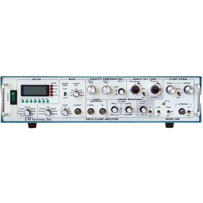
Model 2400 -Patch Clamp Amplifier
The Model 2400 is a low-noise, full-featured patch clamp amplifier designed for voltage clamping using patch electrodes on single channels or whole cells. Its design also allows fast intracellular current clamp measurements with sharp electrodes. Amplifier current gain can be matched to your experimental needs by selecting one of the three available dual resistive feedback probes, as the gain is partially determined by the value of the resistor in the headstage. There are three heastages to choose from: 1 G?/10 M?, 10 G?/10 M?, and 10 G?/100 M?. The wide range of feedback resistors means currents can be recorded with outputs of 1 mV/nA to 10 mV/fA. The standard probe sent with each unit is the 100 M>?/10 G>? version, but other values can be selected.
Unlike other patch clamp amplifiers, the Model 2400 has a voltage follower in the probe. This allows this amplifier to be a true fast current clamp amplifier with no instability. An integrated four pole low pass Bessel filter provides flexible signal conditioning. Fine tuning capacity compensation is available to eliminate virtually all electrode-induced transients. Calibrated whole cell compensation provide easy display of membrane capacitance and access resistance.
A host of command potentials are integrated internally within the model 2400, including an automatic tracking command to zero the membrane current, manual controls for offset and holding potentials, and an easily readable digital display. For signals that are more complicated, an external command input with different scaling factors is available for use with any signal source. A digital meter provides accurate values of command signals and membrane currents or voltages, the true RMS noise of the amplifier and experimental setup, the cut off frequency of the low pass filter, and the overall gain of the amplifier plus probe.
Series resistance compensation provides the researcher with the option of introducing either or both predictive and corrective compensation from zero to 100%. Fine and coarse controls for lag provide sensitive control to minimize oscillation produced by compensation close to 100%. Separate compensation controls exist for eliminating transients seen during current clamp experiments when the bridge balance is used.
Telegraph outputs provide analog voltage equivalents of front panel settings including error conditions, amplifier mode and gain, Cmembrane, RMS noise, and low pass filter cut-off value. These telegraphs allow the Model 2400`s front panel settings to be automatically recorded by your system software.
The Model 2400 Patch Clamp Amplifier from A-M Systems can serve as a high quality research amplifier in your laboratory, or an inexpensive teaching rig in your graduate courses . Please contact us for information about a free Model 2400 “test drive” in your own lab… No purchase required.
- 10 mV/mV-1 V/mV
- 4 pole Bessel filter with 6 pre-set values, and bypass: 0.5 kHz, 1.0 kHz, 2.0 kHz, 5.0 kHz, 10.0 kHz, and 20.0 kHz.
- 0.1 kHz resolution
- Voltage clamp:
- FAST1: 0-10 pF, 0.2-2 µs
- FAST2: 0-1 pF, 0.1-10 ms
- Current clamp
- FAST1: 0-10 pF
- No FAST2
- Raccess: 0-100 M?
- Cmembrane: 0-100 pF
- RsPre: 0-100%
- RsComp: 0-100%
- LagCoarse: 1-100 µs
- LagFine: 1-10 µs
- Up to the value of the low feedback resistor in the probe
- Voltage clamp: ±200 mV
- Current clamp:
- Probe Resistor: 10 M / 100 M
- Command Range: ±200 nA / ±20 nA
- Voltage clamp: ±100 mV
- Current clamp: ±1 V
- Used in voltage clamp only.
- Probe High Gain: 0.2 nA p-p at 60 Hz
- Probe Low Gain: 1 nA p-p at 60 Hz
- ±5 mV at 60 Hz
- ±1 nA at 60 Hz
- Voltage clamp: 100 mV/V with the external switch set to divide by 10, 20 mV/V with the external switch set to divide by 50
- Current clamp:
- Probe Resistor: 10 M? / 100 M?
- /10 Range: ±100 nA/V / ±10 nA/V
- /50 Range: ±20 nA/V / ±2 nA/V
Patch Clamp Electrophysiology
A-M Systems Model 2400 Patch Clamp Amplifier is compatible with pCLAMP, WinWCP as well as Signal. The following description is for CED`s Signal software.
Signal for Windows incorporates many powerful features for whole cell and single channel experiments that make it ideal for electrophysiological recording. Familiar terms, and easily set up protocols for standard requirements enable the user to get started quickly using Signal and a CED Power 1401 data acquisition interface. Signal also incorporates an import function allowing you to analyze data from other recording systems.
Signal can easily all of the stimuli needed, including pre-recorded waveforms to perform voltage and current clamp experiments. In addition, Signal combined with the Power1401-3 data acquisition system are the easiest way to implement Dynamic Clamping in your research protocols.
Multiple sets of stimuli can be stored in one sampling configuration and selected manually or automatically sequenced. Signal can perform on-line measurement of seal and membrane resistance. Leak subtraction and I/V plots can be generated in real time or during offline analysis. Signal also provides mathematical functions to enable complicated curve fitting to waveform data and I/V plots.
Telegraph communication from the A-M Systems Model 2400 Patch Clamp Amplifier allows Signal to set properly scale collected data and send appropriate control voltages to the amplifier for complete control of the recording preparation
Signal can perform complicated curve fitting to your collected measured data, including Exponential, Gaussian, Polynomials, and Sigmoid curve. All data can be plotted and exported in tabular or graphical forms.
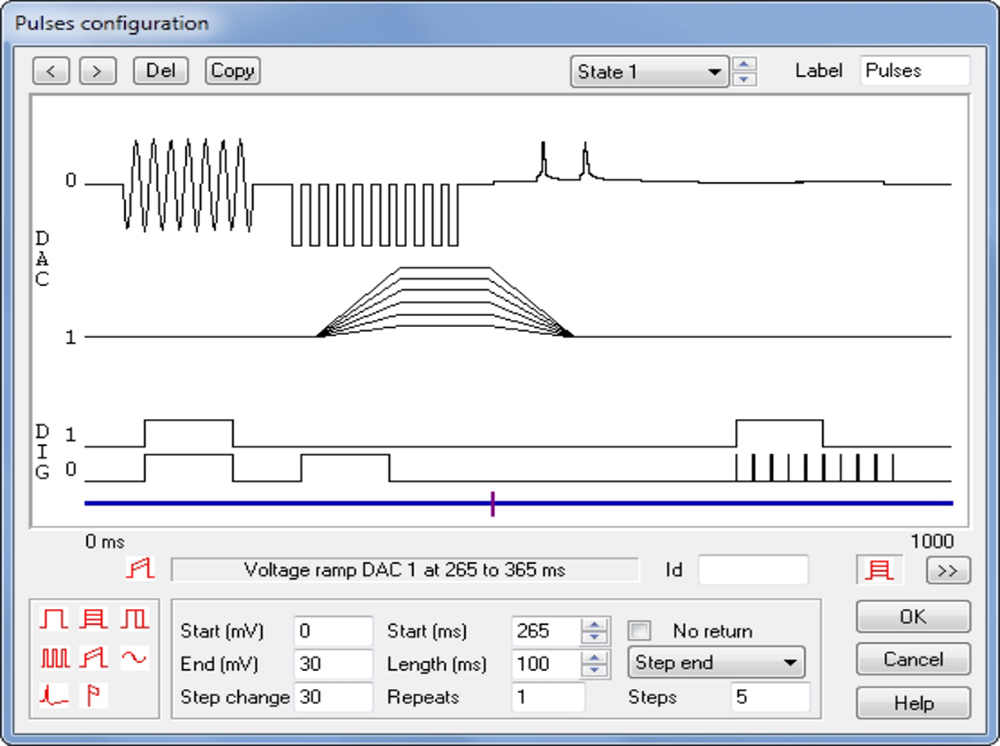
- Generate stimuli on up to 8 DACs and 8 TTL lines.
- Define as many as 256 sets of up to 500 pulses.
- Set stimuli at a fixed level or relative to an adjustable holding potential or current.
- Output multiple sets of arbitrary waveforms per sweep.
- Sequence through sets of pulses manually, cyclically, randomly or by user-defined protocol.
- Interactively edit, add and remove stimuli while recording.
- Define pulses with fixed or stepping amplitudes and durations.
- Pulse types include square waves, ramp, sinusoid, pulse trains and pre-recorded or user-generated waveforms, for example, recorded action potentials.
- Nominate a particular recording state to be used for seal and membrane resistance measurements.
- Easy adjustment of holding potentials.
- Dynamic readout of seal resistance.
- Membrane analysis option displays measurements of total resistance, access and membrane conductance, capacitive transient decay time constant and membrane capacitance.
Signal and the Power1401-3 data acquisition system are the easiest way to implement Dynamic Clamping in your research program. Signal includes a fully integrated, easily configurable, high-performance dynamic clamping system. This advanced feature makes the technique readily available to researchers who do not have access to complex customized hardware and software, by providing a professionally designed, maintained and supported package that is usable by all, at a low cost.
In the dynamic clamp technique, a typically nonlinear feedback system delivers current to a cell to represent the actions of virtual ion channels, allowing ion channels or synapses to be simulated or the actions of existing channels to be cancelled.
When used in conjunction with the Power1401-3, Signal can be the bases of your dynamic clamp environment. Standard embedded hardware-based dynamic clamp systems offer feedback that is fast and precisely timed, but these systems are often expensive and sometimes inflexible. PC-based systems, on the other hand, allow more complex feedback, but real-time performance can be poor.
The CED Signal dynamic clamp system gives you the best of both worlds. All real-time aspects of the system are executed by the Power1401`s fast embedded processor using pre-calculated lookup tables and optimized floating-point arithmetic, with the feedback calculations triggered by the ADC sampling for maximum stability. This software-based design is quick yet still provides great flexibility. The non-real-time aspects of the system are handled by the controlling PC to allow simplicity and ease of use.
The result: a dynamic clamp system integrated into the standard Signal data acquisition software that outperforms generally available dynamic clamp systems, at a reasonable cost.